


Upgrading Your Boat’s Electronics: Raymarine Refit & Network Setup Guide
Upgrading aging marine electronics is one of the most effective ways to boost safety, improve navigation clarity, and increase your boat’s market value. However, transitioning from legacy displays to a modern, fully networked Raymarine ecosystem involves much more than swapping screens on the helm dashboard.
From building a reliable NMEA 2000 backbone to calculating DC power loads and mounting thru-hull transducers, a successful refit requires structured planning. This comprehensive guide covers key considerations for upgrading to modern Raymarine gear and highlights where professional installation protects your investment.
Mapping the Raymarine Data Network: NMEA 2000 & RayNet
Modern Raymarine systems rely on two distinct networking standards working in tandem:
- SeaTalkng / NMEA 2000 (Low Bandwidth): Handles numeric and sensor data such as GPS position, wind speed, engine telemetry, depth, and autopilot commands.
- RayNet Ethernet (High Bandwidth): Transmits heavy data streams including high-definition sonar imagery, Quantum radar signals, and multi-display chart sharing across Axiom MFDs.
When retrofitting an older boat, mixing legacy SeaTalk1 devices with modern SeaTalkng networks requires dedicated converter kits and power-isolated spurs. Incorrectly terminated NMEA backbones cause data dropouts and erratic autopilot performance.
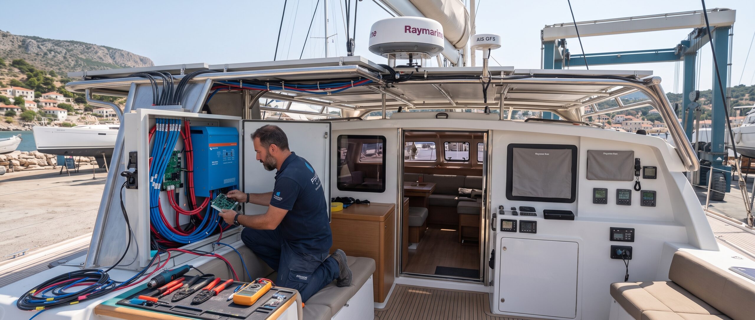
Need assistance with complex marine wiring? The certified technicians at Pharos Marine design and build custom NMEA 2000 backbones tailored to your vessel’s layout, ensuring seamless data flow across all instruments.
Power Load Management & Circuit Protection
Modern high-brightness displays, CHIRP sonar modules, and open-array radars draw significantly more current than older instruments.
| Raymarine Component | Average Power Draw | Wiring Requirement |
| Axiom 2 Pro 12″ MFD | ~30W / 2.5A @ 12V DC | Dedicated fused circuit, minimum 14 AWG wire |
| Quantum 2 Doppler Radar | ~17W (Transmit) | Direct breaker connection, heavy-gauge run to mast/arch |
| Evolution Autopilot (ACU-200) | Up to 15A (Peak load) | Heavy battery feed with isolation switch |
Voltage drops cause chartplotters to reboot during engine starts or high-load maneuvers. During any electronics refit, auditing the vessel’s DC breaker panel and upgrading wire gauges is vital.
Transducer Selection & Mounting Pitfalls
Choosing between transom-mount, in-hull, or thru-hull transducers depends entirely on hull material (solid fiberglass, cored fiberglass, metal, or wood), deadrise angle, and cruising speed:
- RealVision 3D & CHIRP Thru-Hull Units (RV-200 / RV-300 Series): Designed for high-speed tracking and sharp bottom imaging, thru-hull transducers require precise spatial alignment. Dual element pairs (port/starboard) must account for hull deadrise angles (0 to 24). Off-axis tilt alignment leads to corrupted 3D spatial rendering and signal attenuation.
- Acoustic Shadowing & Laminar Waterflow: Mount locations must sit forward of strakes, steps, underwater pickups, and the propeller plane. Placing elements in aerated, turbulent water degrades CHIRP side-vision frequency sweeps (350kHz-1.2MHz).
- Fairing Block Shaping & Structural Hull Integrity: Fitting thru-hull bronze or stainless steel housings demands custom-shaped fairing blocks matched to deadrise angles to maintain a true parallel aspect to the waterline. Core-bonding epoxy technique is critical on cored fiberglass hulls: un-cored sleeve inserts must seal exposed balsa or foam cores to prevent catastrophic hydraulic water intrusion. Applying anti-fouling-compatible, non-copper underwater marine sealants (like 3M 4000-UV or Sikaflex 291i) prevents galvanic corrosion and seal degradation.
Radar & Autopilot Calibration
Mounting hardware is only half the battle. Once installed, complex Raymarine systems require precise digital calibration:
- Radar Electronic Bearing Alignment (EBA): Heading misalignment off the physical keel center line distorts target tracking. Setting the Electronic Bearing Line (EBL) relative to the bow vector ensures AIS targets, ARPA radar tracking, and optical targets sync cleanly across overlay charts.
- EV-1 Core Sensor Linearization & Deviation Mapping: Raymarine’s 9-axis Evolution sensor core continuously monitors vessel roll, pitch, and yaw. During sea trials, the system performs dynamic magnetic deviation mapping. Surrounding onboard magnetic interference (iron keels, high-current DC cables, engine blocks) must be compensated for via automated 360 linearization turns to bring compass deviation below 5.
- Rudder Reference Unit (RRU) & Hydrodynamic Tuning: Setting hard-over to hard-over limits, deadband thresholds, and rudder gain parameters prevents over-steering oscillation, reducing hydraulic pump amp-draw and wear under heavy seas.
Upgrade Your Boat with Pharos Marine
Whether replacing a single display or commissioning a complete helm overhaul, expert installation ensures your equipment performs reliably when weather conditions deteriorate.
At Pharos Marine, we specialize in the supply, custom helm integration, and on-site installation of the complete Raymarine lineup.
Explore our Raymarine range or get in touch with the Pharos Marine installation team today to request a quote for your next boat refit!